Electronics and Wiring
This chapter describes the electrical architecture of Asimov 1, including how power and CAN are distributed, how the actuator branches are organized, and which joints require special wire routing considerations.
1. Wiring Topology Overview
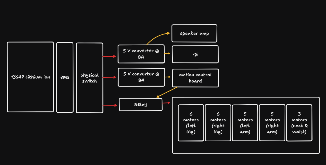 Figure 1. System-level wiring architecture.
The robot wiring is organized as multiple parallel branches. Each limb or body section forms one branch, and the actuators within that branch are connected in series from one joint to the next.
Examples:
- Left leg:
hip pitch -> hip roll -> hip yaw -> knee -> ankle A -> ankle B - Right leg:
hip pitch -> hip roll -> hip yaw -> knee -> ankle A -> ankle B
Each branch begins at a joint near the main body and continues outward through the rest of the limb or module.
2. Actuator Ports and Signals
Each actuator has two ports using an XT30 (2+2) connector.
For wiring purposes, these may be treated as input and output ports, but electrically they are equivalent and internally shorted together. There is no fixed electrical direction between the two ports, so either one may be used depending on routing convenience.
Each 4-pin port carries:
BATT+BATT-CAN_HCAN_L
Because both ports are electrically equivalent, the chosen port at each actuator is determined by physical cable routing rather than by a required port direction.
3. Hollow-Shaft Routing Constraints
Certain actuators use a hollow shaft to allow wires to pass through the joint. This enables compact internal routing, but it also limits when connectors can be attached because the connector body may not fit through the shaft opening.
For these joints, the wire must be routed through the required path before the final connector is attached.
Hollow-shaft joints:
hip rollhip yawshoulder pitch
Post-routing connector locations:
- at the
hip roll, for the connection to thehip yaw - at the
knee, for the connection along thehip yawrouting path - at the
shoulder roll, for the connection to theshoulder pitch
These routing constraints should be considered when preparing cable assemblies and planning cable termination.
4. Branch Entry Points
Each actuator branch starts at a joint close to the robot body and continues outward through the corresponding limb or module.
At each branch-entry actuator:
- the
CAN_HandCAN_Lpair connects back to the Motion Control Board - the
BATT+andBATT-pair connects to the robot power bus throughXT30
The branch-entry actuators are:
- left hip pitch
- right hip pitch
- waist yaw
- left shoulder pitch
- right shoulder pitch
- neck yaw
These joints serve as the entry points for daisy-chained actuator wiring in each branch.
How is this guide?