Understanding Your Simulation Environment
This chapter describes what the locomotion simulator is expected to represent, what it intentionally does not represent, and why those boundaries matter for sim2real transfer.
1. Simulation is part of the control stack
For Asimov, the simulator is not treated as an isolated physics sandbox. It is treated as one component in a larger control stack that includes:
- the robot kinematic and dynamic model
- actuator behavior and delay
- sensor noise and observation timing
- the firmware path used to compute control-relevant signals
- the policy observation and action interface
This viewpoint is important because many real deployment failures are not caused by large physics mismatches. They are caused by timing skew, stale observations, bus jitter, or control signals that are computed differently in simulation and on hardware.
2. Scope of the locomotion model
The current locomotion stack is built around the legs-only robot:
- 12 actuated joints across both legs
- 2 passive toe joints
- a parallel ankle mechanism rather than a simple directly driven serial ankle
The simulator uses rigid-body dynamics, but needs to capture more than simple serial-chain kinematics. It also needs to reflect:
- ankle pitch and roll mapping through the parallel mechanism
- passive toe compliance and toe-ground interaction
- actuator saturation, friction, and delay
- contact geometry under the foot and toe
3. Simulator rates and control rates
The training environment uses separate rates for physics, IO, and policy execution.
Here, IO means the observation and actuator-side update path, not policy inference itself. It is the loop that carries raw motor-state timing, observation delay, and control-path bookkeeping before the policy consumes the resulting state.
| Layer | Rate | Role |
|---|---|---|
| Physics step | 200 Hz | Integrates robot dynamics |
| Observation / IO path | 200 Hz | Updates motor-state and actuator-side signals, including timing and delay effects |
| Policy step | 50 Hz | Produces commanded joint targets from the latest available IO state |
These separate rates matter because the policy is not trained on infinitely fresh simulator state. It is trained on data that already reflects timing artifacts in the control loop.
4. Do not trust pristine simulator data
A default simulator exposes perfectly synchronized state:
- all joint observations arrive at once
- sensor values are available without bus latency
- actuators respond at fixed timing
- projected gravity and orientation can be computed from ideal simulator state
This is useful for debugging, but it is not the data that real hardware provides. The locomotion stack therefore avoids building the policy around privileged measurements that do not exist on the robot.
5. Processor-in-the-loop environment
Asimov extends the simulation boundary beyond rigid-body dynamics by running the real firmware path inside the validation loop.
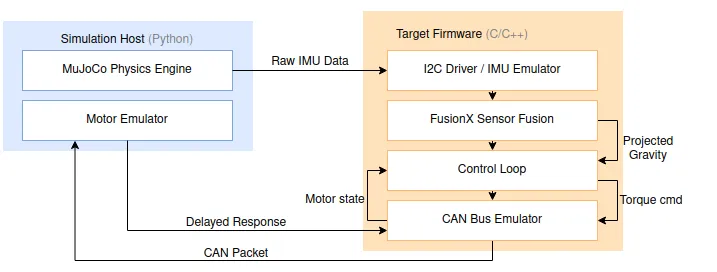
Figure: Processor-in-the-loop architecture used for sim2real validation. The important point is that the control loop is closed through the real firmware path, with MuJoCo providing simulated IMU signals and the communication stack preserving the same software interfaces used on the robot.
The processor-in-the-loop path includes:
- virtual CAN on Linux through the same SocketCAN software interface used by the motor stack
- a MuJoCo bridge that reads
imu_ang_velandimu_lin_acc - UDP transport of simulated IMU data into firmware
- the same FusionX path used on hardware to compute projected gravity for the policy
This design avoids a common failure mode where simulation uses a simplified software path that cannot exist on the real robot.
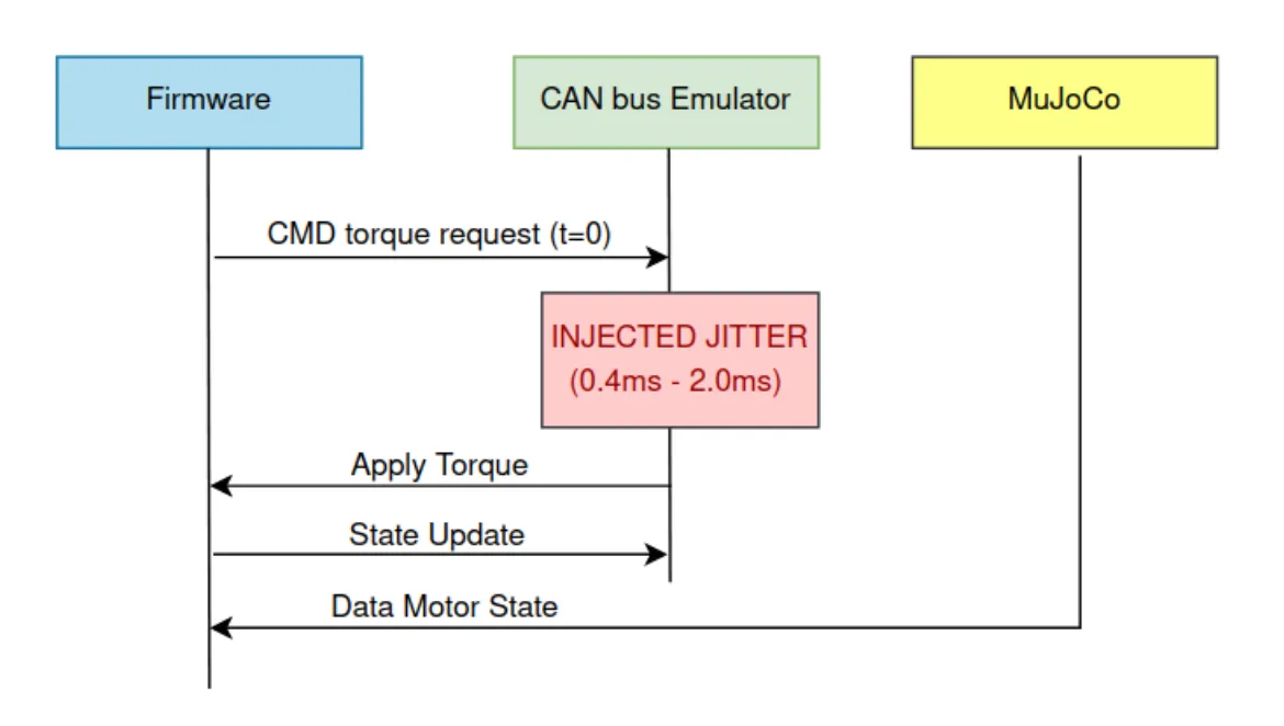
Figure: CAN bus delay and jitter injection used to test timing robustness before hardware deployment. This figure is included here because locomotion transfer depended not only on rigid-body physics, but also on whether the simulated control path exposed the same latency variation and stale-data behavior seen on the real system.
6. Contact geometry and collision stability
Foot-ground contact must be stable and interpretable. For this reason, the locomotion environment uses explicit collision primitives instead of relying on detailed mesh collision for learning.
Key choices include:
- capsule-based foot and toe contact geometry
- explicit toe and foot contact points
- contact tuning on foot and toe geometry
- conservative, repeatable contact behavior rather than maximum geometric fidelity
This reduces the risk that the policy learns from unstable collision artifacts.
7. Hardware structure still constrains the simulator
The simulation environment is specific to the Asimov leg design, not a generic humanoid simulator. The hardware constraints that shape the simulation — the parallel ankle mechanism, passive toe joints, actuator limits, and joint ranges — are documented in Joint Design and Actuation and Deep Dive: System Identification.
How is this guide?